3 Wire Speed Sensor Wiring Diagram
40+ 3 Wire Speed Sensor Wiring Diagram Background. Testing either a 2 or 3 wire (hall effect) speed sensor is a relatively easy task, and one that can save you quite a bit of money in the long run. In basic diagram, there are four wires that connect to the motor:
Connect gnd to arduino as well as.
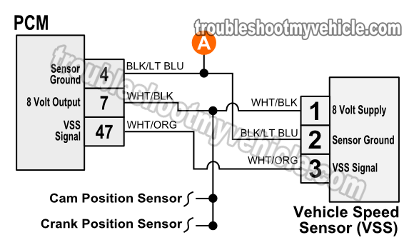
Wiring diagram of external map sensor. On my truck, one is black/orange and comes from the gauge fuse, so i'm presuming that it is close perusal of my fsm (the section of the wiring diagram labled combination meter) along with the speed sensor wiring yielded the following info Use multiple technologies to detect a change in a rotating, ferrous metal. This diagram is a thumbnail.

0 Response to "3 Wire Speed Sensor Wiring Diagram"
Post a Comment